Digital Alarm Clock
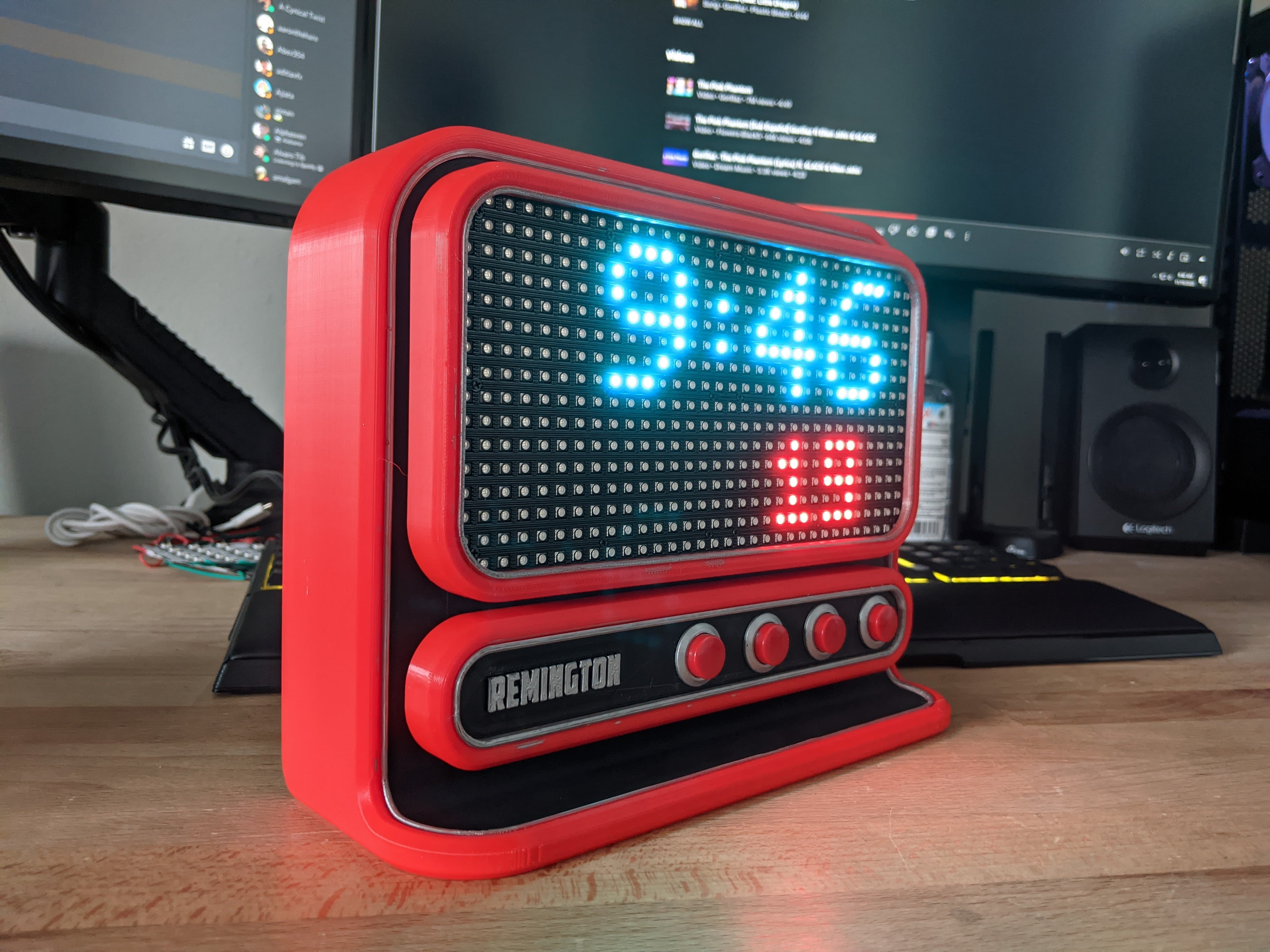
A digital alarm clock with a custom designed, PCB and housing.
An embedded digital alarm clock with a custom engineered PCB and 3D printed chassis.
This project was completed as part of my Embedded Systems Fabrication course. In the course, we learned the skills necessary to turn an embedded device prototype into a mass-manufacturable product by creating a digital alarm clock.
Throughout the course, we had the opportunity to design formal schematics for the clock in our EDA software of choice (I used Altium Designer), convert those schematics into a PCB, order those PCBs from a PCB fabricator, assemble those PCBs, then execute the firmware bring-up for the device to make sure everything is working as expected.
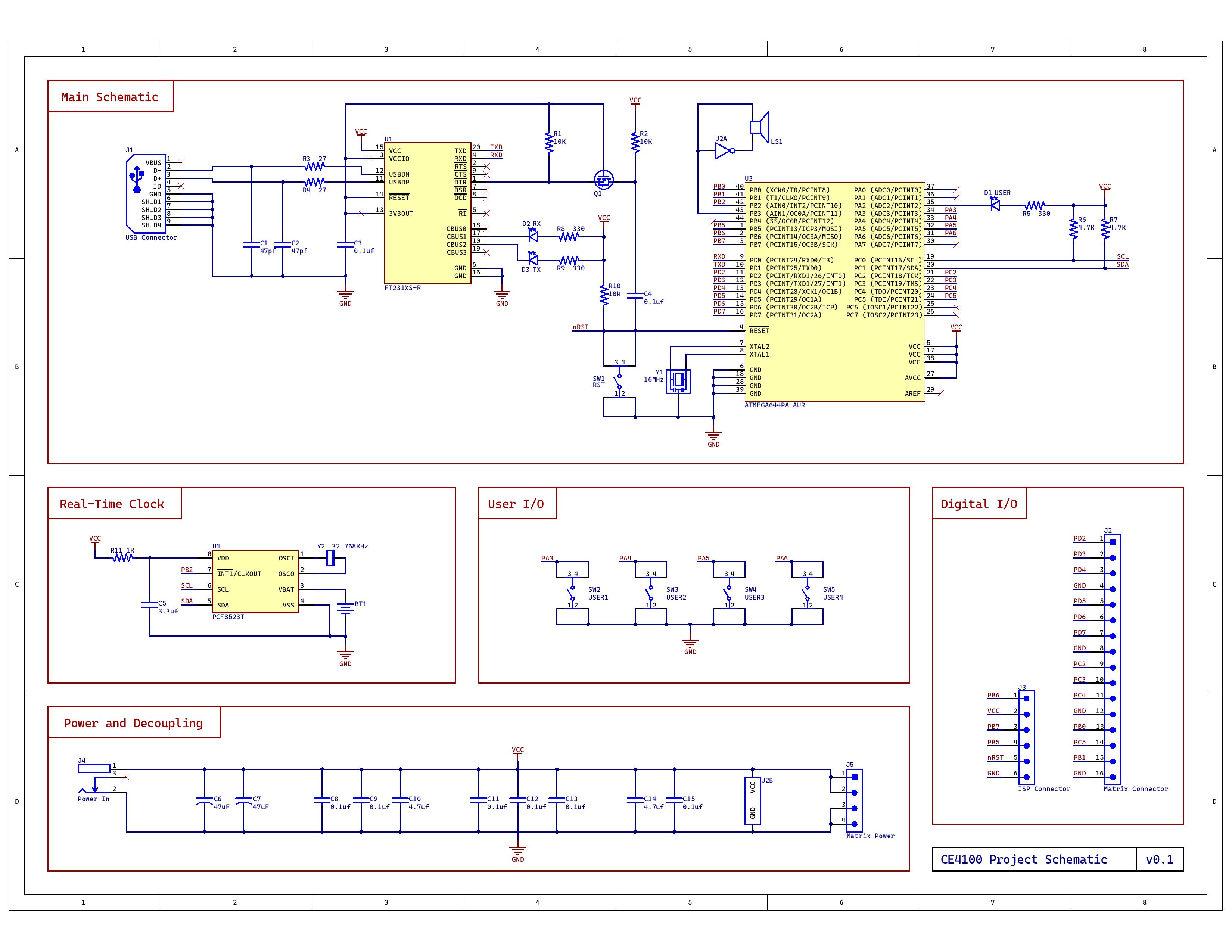 The clock PCB schematic made in Altium.
 The clock PCB layout made in Altium.
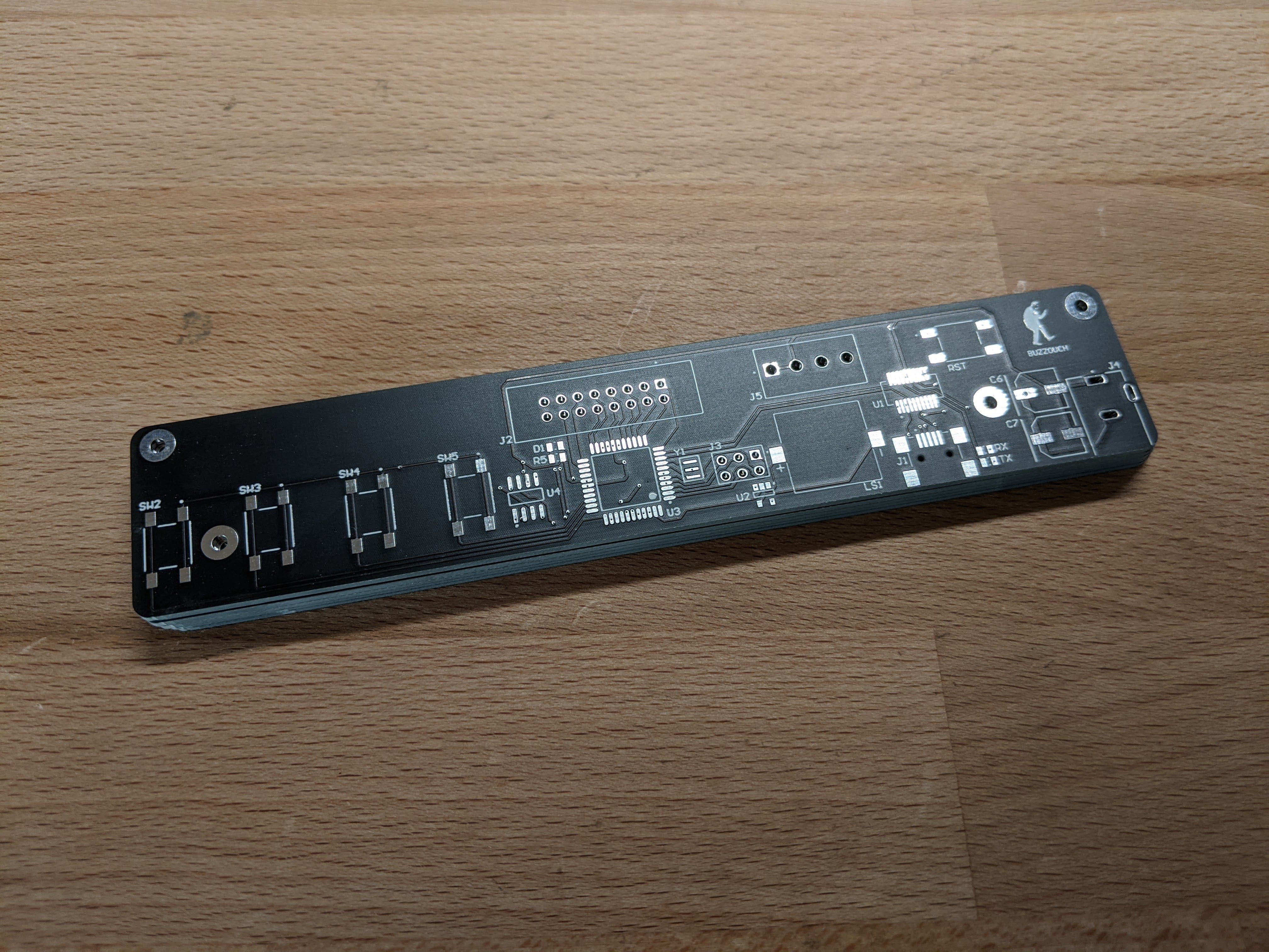 The fabricated PCB from JLCPCB.
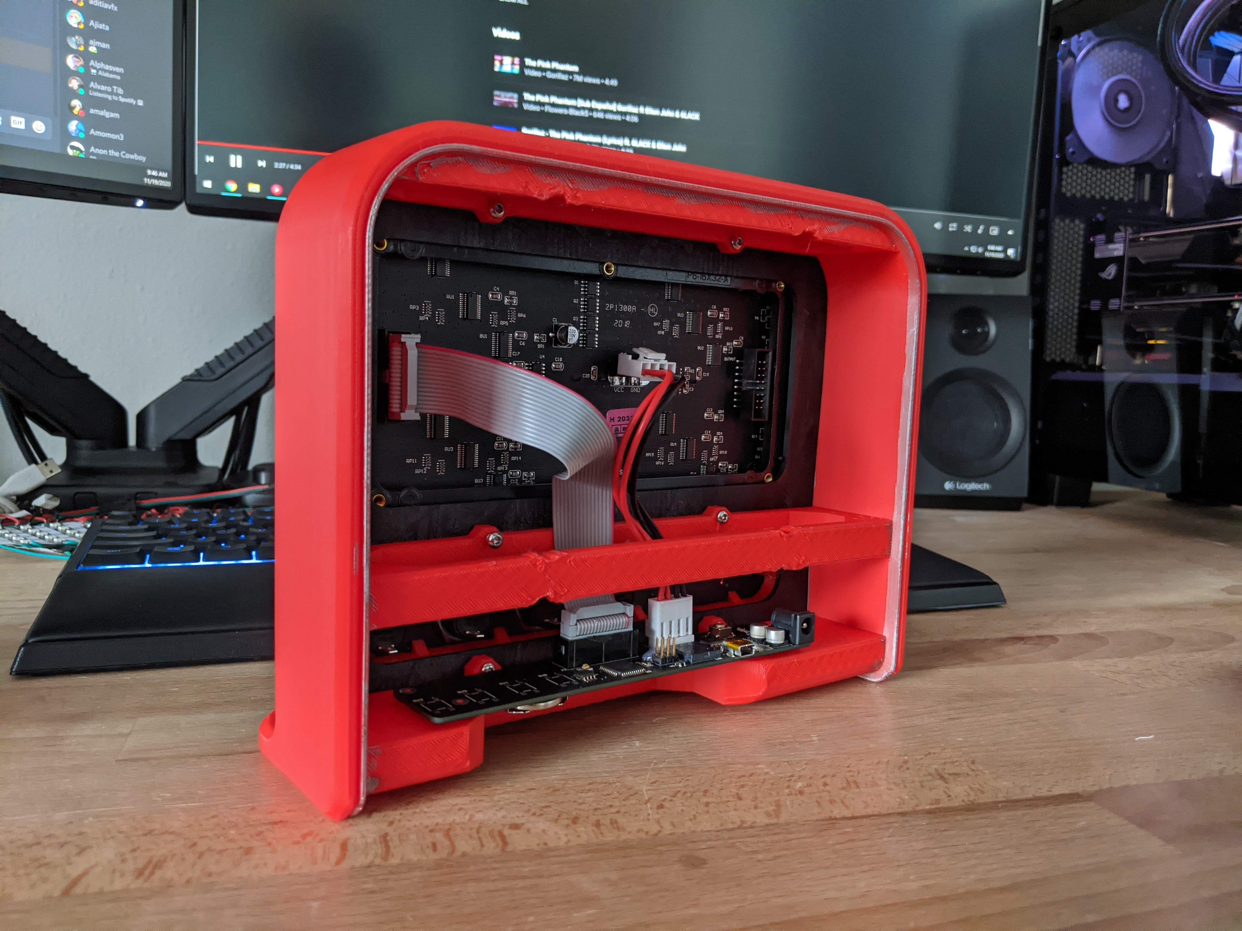
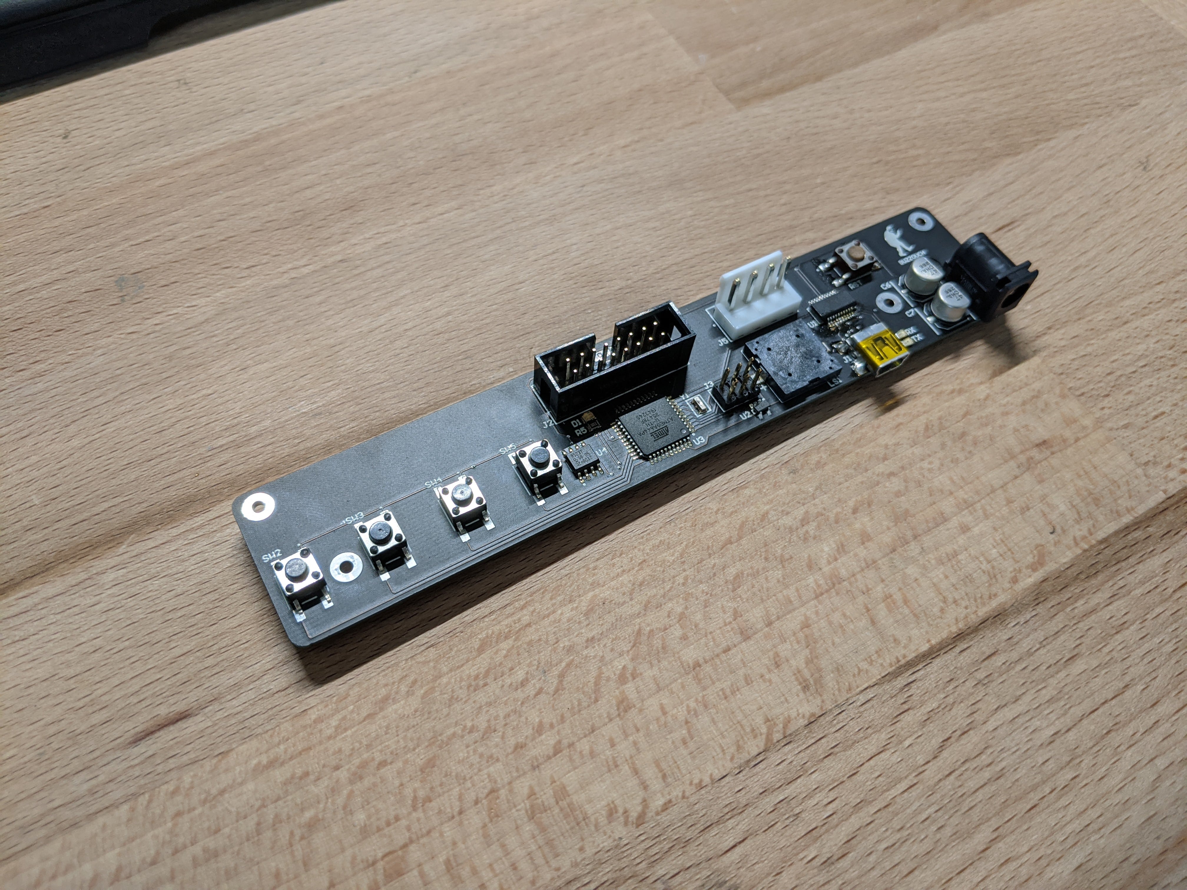 The populated PCB, done with reflow and hand soldering in MSOE’s EECS maker lab.
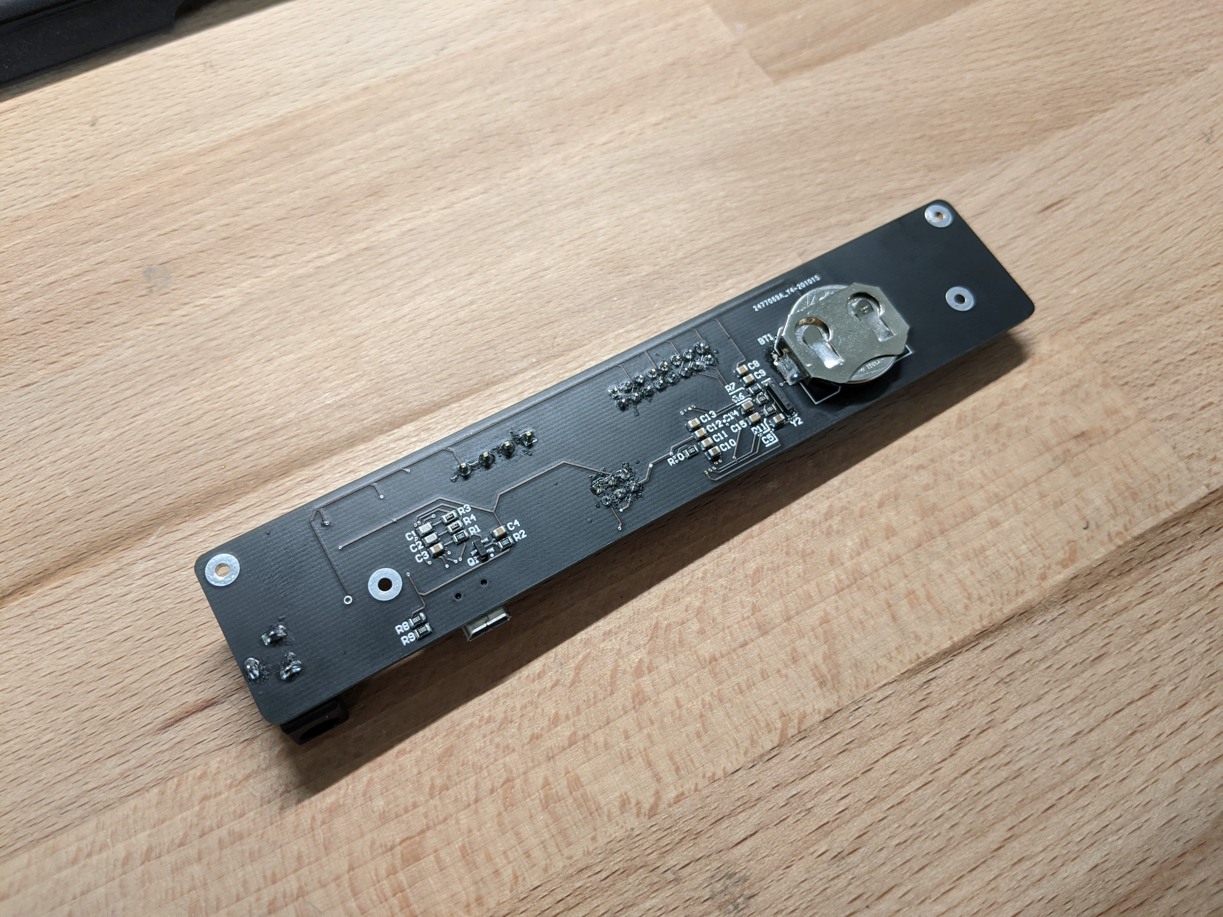 The backside of the populated PCB. I was the only person in my class to make a 2-sided PCB.
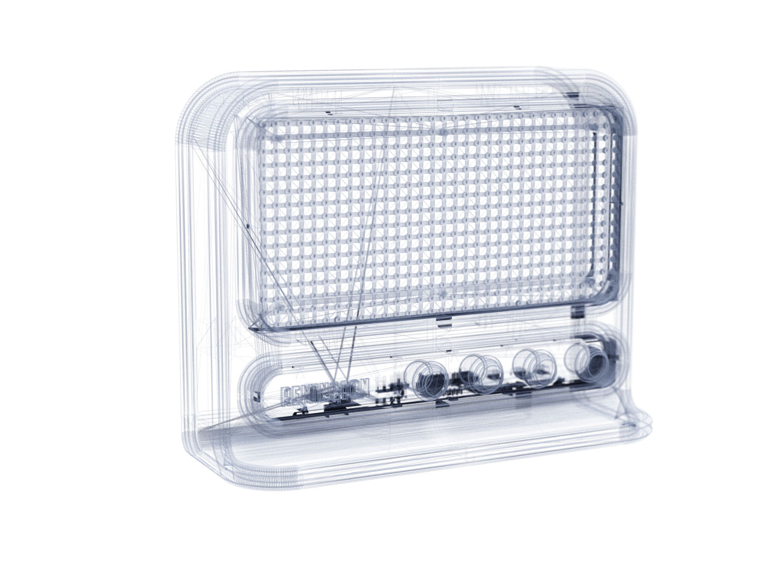
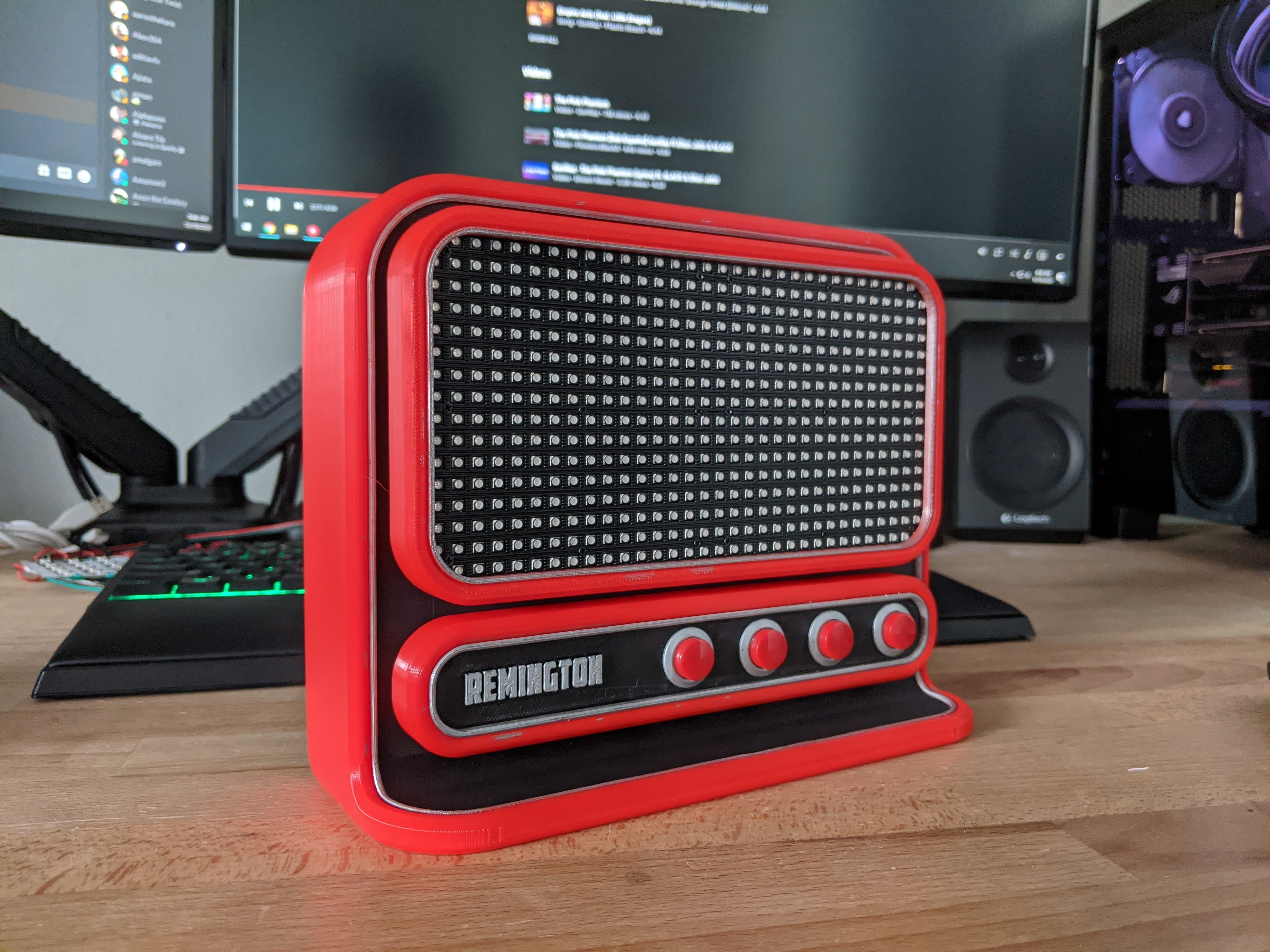
In addition to designing the electronics, we also had the opportunity to play around with our favorite CAD tools to design a housing for our alarm clock. Having spent 6 years prior as a professional 3D artist, I was BEYOND excited about this, and had a wonderful time designing a custom housing using Blender.
We later 3D printed these, which was also a fun challenge given the relatively large size of each print.
I was beyond impressed with the results from this project. It was crazy cool to see an idea go from a few specifications on paper to something so real and tangible. The class this project was completed for was by far one of my favorite classes I’ve taken in my studies, and I’m eager to apply these new skills in some personal projects.
As for the clock… it now makes for a nice time-keeper in my personal work bench at my apartment.
